The flight controller is installed on the aircraft for the first time, and you can use the assistant software to perform the following basic function setting steps before normal flight.
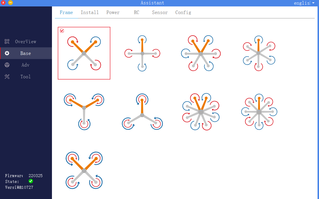
1. Rack selection
Click to enter the basic interface of the assistant software, select the rack in the upper menu bar, as shown in the figure, and select the correct rack according to the actual flight control aircraft. The direction of the yellow arm in the picture is the head direction.
2. Installation settings
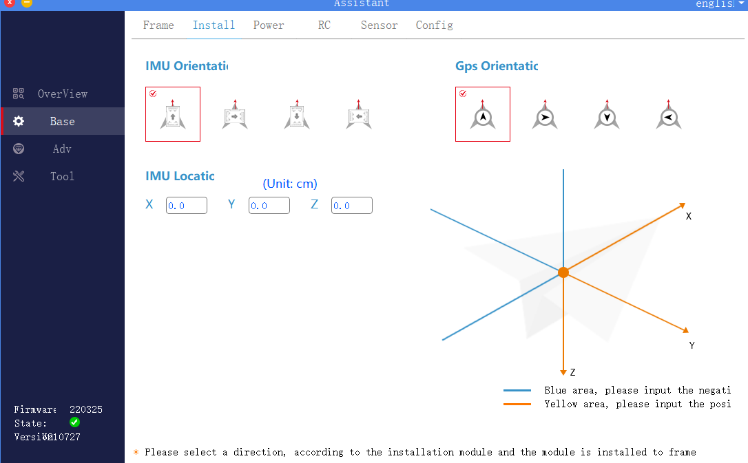
Click to enter the basic interface of the assistant software, select installation from the upper menu bar, as shown in the figure, choose the correct orientation according to the actual installation direction of the flight controller and GPS.
1) .IMU orientation
The direction of the IMU is the installation direction of the flight controller. The red arrow facing the IMU indicates the nose direction, and the gray arrow on the flight controller indicates the direction of the flight controller. The wrong choice can lead to serious flight accidents.
2) .GPS orientation
The red arrow of the GPS direction indicates the nose direction, and the black arrow of the GPS direction indicates the GPS direction. Please ensure that the set GPS direction is consistent with the actual GPS installation direction. If using dual GPS modules, please ensure that the two GPS installation directions are the same. The wrong choice can lead to serious flight accidents.
3) .IMU location
For users with high requirements for flight performance, ordinary users can leave it alone. According to the distance between the flight controller and the center of gravity of the aircraft, fill in the IMU installation position correctly.
3. Power configuration
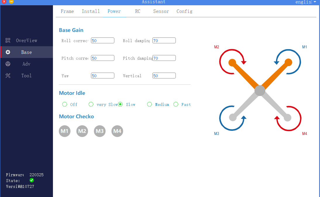
Click to enter the basic interface of the assistant software, select the power configuration in the upper menu bar, as shown in the figure, including basic sensitivity settings, motor idle speed selection, motor sequence detection and motor serial number.
1). Basic sensitivity setting
Basic sensitivity includes roll correction, roll damping, pitch correction, pitch damping, yaw, and vertical. It is mainly used to adjust and adapt to the rack. The function definition of each sensitivity is shown in the table.
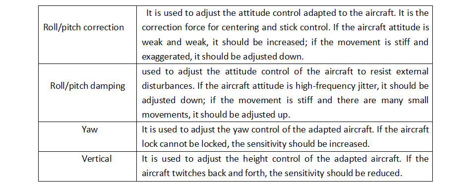
Basic sensitivity debugging steps:
a. First adjust the vertical sensitivity, adjust it under no-load conditions, and slowly increase the vertical sensitivity until the aircraft twitches up and down, and then adjust the sensitivity back to no twitch.
b. Adjust the roll / pitch damping sensitivity again, and slowly adjust it from low to high according to 10%, until the aircraft appears high frequency jitter or the motor noise increases significantly, then fine-tune the sensitivity back to normal conditions.
c. Then adjust the roll / pitch correction sensitivity, press 10% slowly from low to high, until the aircraft shakes, the motor sound is abnormal or exaggerated, and then adjust the sensitivity back to normal conditions.
d. Finally adjust the yaw sensitivity. In general, if the default parameters do not appear to lock the head, you do not need to adjust it. If the head does not lock, increase the sensitivity.
2). Motor idle speed selection
It is used to set the idle speed of the motor after the aircraft is unlocked. Disabled means not to rotate. From very slow to fast, it means that the speed that can be reached by clicking is faster.
3). Motor sequence detection
Used to test the rotation direction of the motor. When using this function, connect the power battery and remove the propeller.
~ M4, the corresponding motor will rotate at idle speed. Please ensure that the motor serial numbAfter clicking the circular buttons M1 ~ M4, the corresponding motor will rotate at idle speed. Please ensure that the motor serial number, steering and diagram are consistent.
4 Remote control settings
Click to enter the basic interface of the assistant software, and select the remote control in the upper menu bar. As shown in the figure, you can select the remote control type, remote control flight mode channel settings, and runaway protection settings according to actual requirements.
1) .Remote control type
K ++ V2flight control currently supports SBUS type remote control.
2) .Remote control calibration
Note: The remote control must be calibrated when using or replacing the remote control for the first time.
Click the “Joystick Calibration” button to start the joystick calibration. Turn on the remote control at the same time, and move all the joysticks of the remote control back and forth between the maximum and minimum positions, and confirm that channels 1 to 4 of the remote control are roll, pitch, throttle, and yaw respectively. After calibration, return 1 ~ 4 channels of the remote control to the middle position, and then click the “Calibration End” button.
3) .Flight mode setting
The 5 channels of the remote control are used to map the flight mode. Three flight modes can be set in the K ++ V2assistant software: ATT (attitude mode), manual operation (GPS mode), and AB execution (AB operation mode). Subsequent chapters will explain each flight mode in detail. By default, the three positions of the 5 channels are all ATT mode. The user can click the drop-down menu to the right of the three positions to select another mode.
4). Runaway protection settings
Runaway protection is used to set the flight behavior of the remote control when it is out of control, including automatic return, automatic landing, automatic hovering and landing after hovering.
5). Run out of control to continue route setting
When the out-of-control continue operation option is enabled, the out-of-control protection will not be performed after the remote control is out of control in the operation mode (AB operation, route operation), but the operation task will continue to be performed. It is recommended to use this function with the radar.
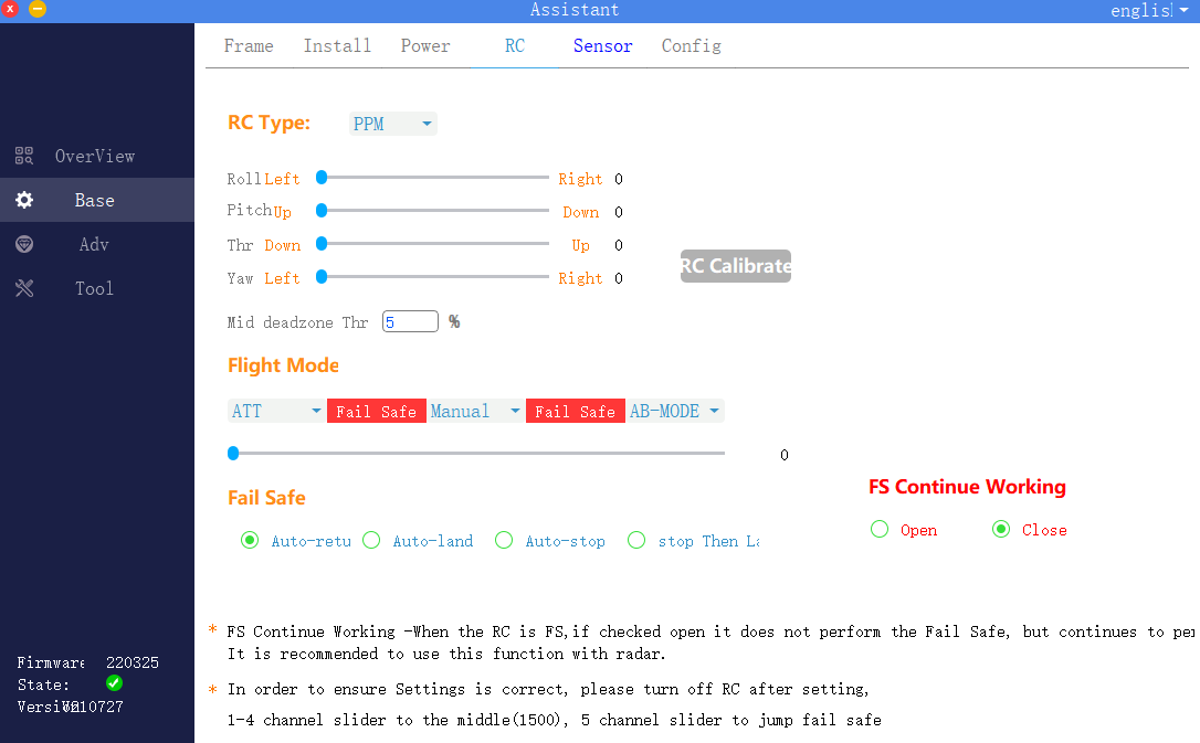
5.Sensor
Click to enter the basic interface of the assistant software, select the sensor in the upper menu bar, as shown in the figure, check the flight control IMU and GPS sensor parameters, and perform accelerometer calibration and magnetic compass calibration. When you click calibration, the assistant software will prompt Instructions, just follow the interface instructions.
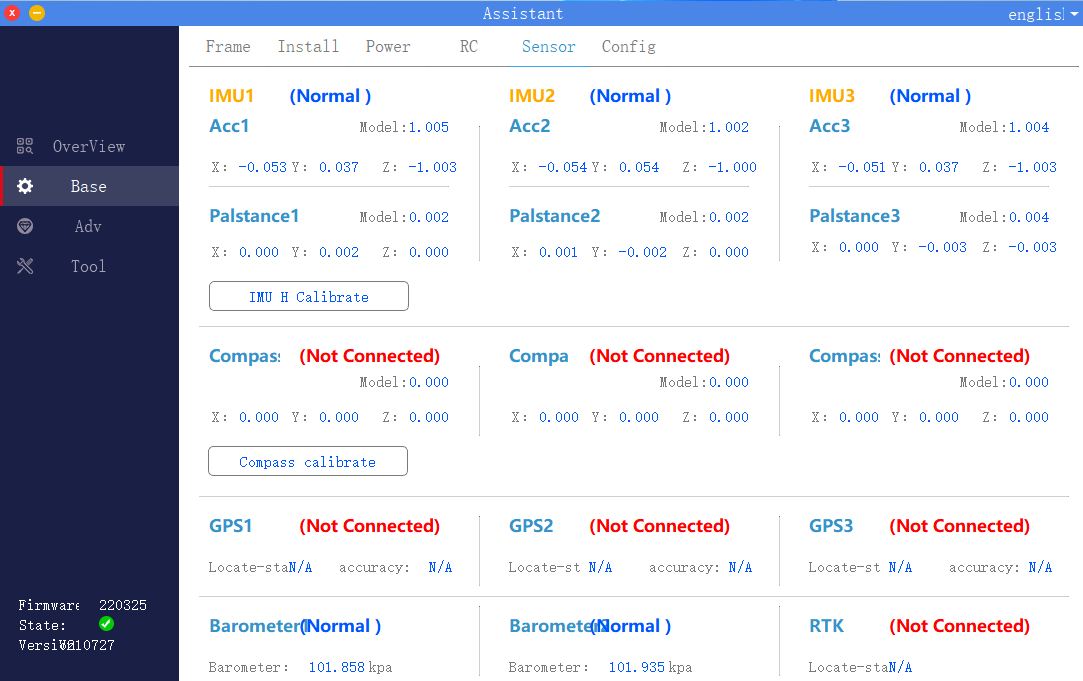
1) .IMU calibration
Place the plane horizontally and click the “IMU Horizontal Calibration” button. Calibration will be completed after 3 seconds. If the body is placed at an inclined angle during calibration, or if it is shaken, it needs to be recalibrated.
2). Magnetic compass calibration
Click the “Magnetic Compass Calibration” button, the LED yellow light is always on, and enter the horizontal calibration. As shown in the figure, at this time, place the aircraft horizontally, rotate the nose clockwise until the LED green light is always on, and enter vertical calibration. As shown in the figure, at this time, the nose is facing downwards and rotated clockwise until the LED red, green and yellow flash alternately, and the calibration is completed.

Precautions:
a. When the flying field changes, the magnetic compass needs to be recalibrated.
b. Before calibration, please check if there is strong magnetic interference nearby.
6. Flight parameters
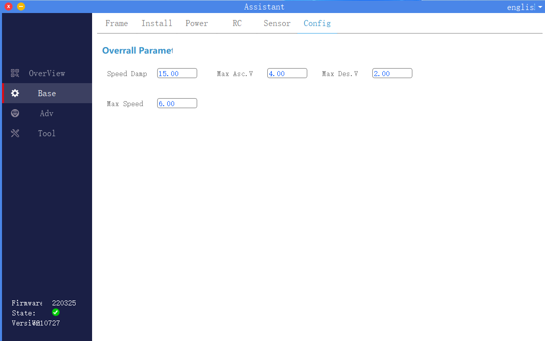
Click to enter the basic interface of the assistant software, and select flight parameters in the upper menu bar. As shown in the figure, the user needs to set the aircraft flight speed related parameters according to the actual model and operating environment.
Maximum tilt angle: The maximum tilt angle in all flight modes.
Maximum Ascent Speed: In addition to the Attitude Mode, the maximum ascent speed that the pilot can control.
Maximum descent speed: In addition to the attitude mode, the maximum descent speed that the pilot can control.
Maximum flight speed: Maximum horizontal speed in attitude mode and GPS mode.
