Including equipment: K++ flight control, CAN Hub, imitation radar, obstacle avoidance radar, RTK, KBOX-4, H12 remote control, agricultural assistant APP.
Take the following X4 model and 10KG aircraft as an example. The flight control installation direction is forward and the GPS installation direction is forward; the RTK main antenna is on arm 2 and the secondary antenna is on arm 1 with symmetrical positions;
Note:
1. Select H12 as the remote control type;
2. Select the expert version for the main interface style;

3. Advanced setting password: 8888;
4. What to do if the advanced settings interface cannot be found:https://support.jiyiuav.com/docs/skoda/skoda-1c8tjn49da22j
Please carry out flight control parameter debugging in the following order, (the part marked in red for parameter modification or key confirmation, please install the part marked in red for setting):
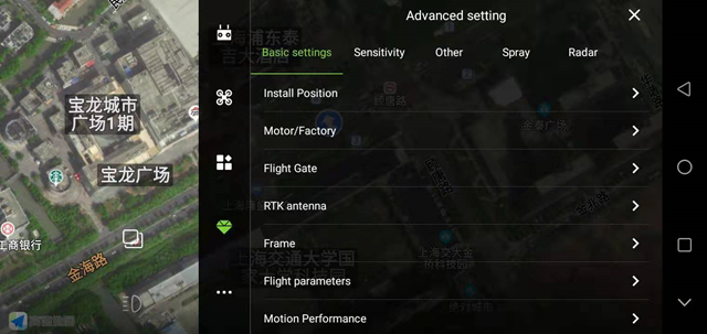
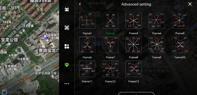
Set according to the actual model, please save it;
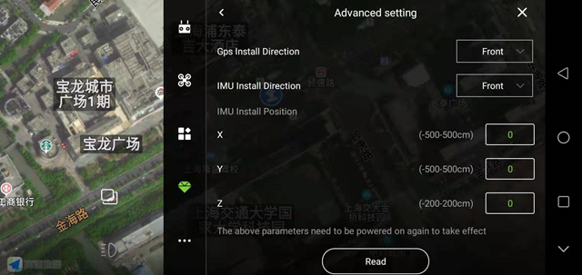
Check the actual installation direction of the aircraft and set the correct GPS and IMU installation direction;
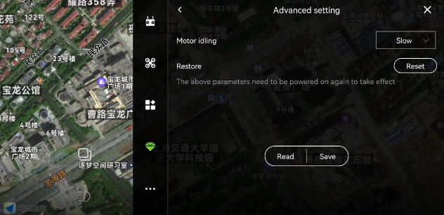
The motor idling speed is generally set to slow speed;
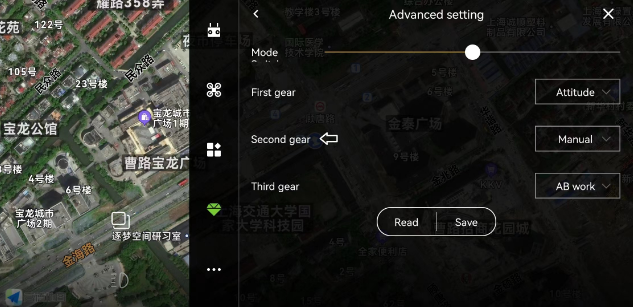
A three-stage switch is required, which are set to: attitude, manual operation and AB operation (or M+);
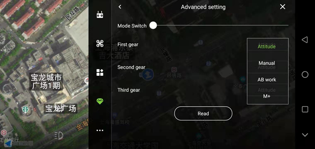
RTK Antenna
1. RTK antenna installation angle setting;
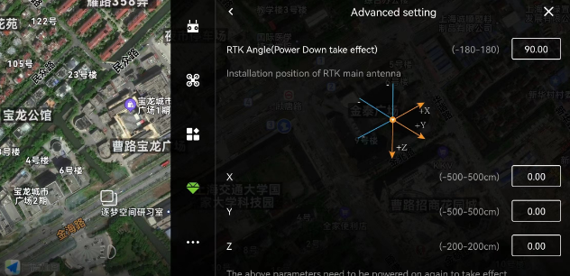
2.J-RTK
For new RTK devices, you need to click “Activate”;
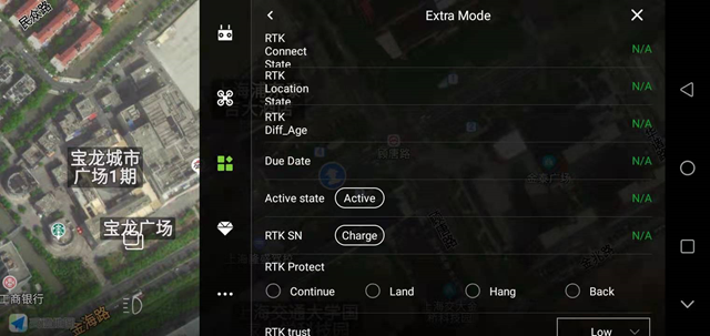
RTK trust: high, medium, low; generally when RTK is installed, set it to medium;
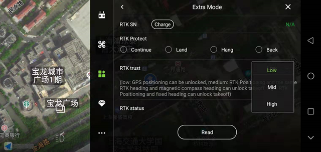
High: RTK positioning and fixed heading, can be unlocked for takeoff;
Medium: RTK positioning and the RTK heading is consistent with the magnetic compass heading, and takeoff can be unlocked;
Low: GPS positioning can be unlocked;
RTK fault protection is set to: continue;
Flight parameters
Keep the default parameters.

Mobility performance
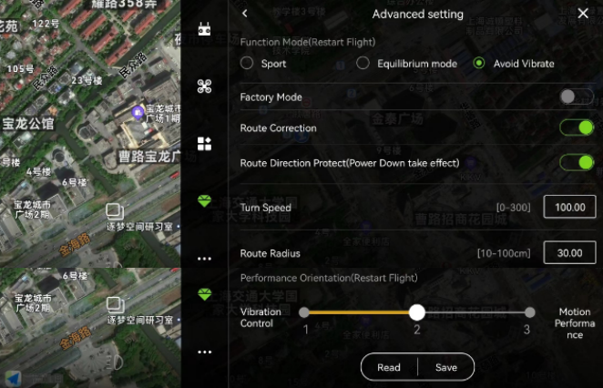
Performance mode: generally choose the anti-seismic mode (depending on the aircraft performance);
Factory mode: When turned on, the height limit will be increased to 500m and the speed will be increased to 15m/s.
Track correction: enabled by default;
Course protection function: It is recommended to turn it on. When the GPS direction is inconsistent with the actual direction, it can protect the aircraft from bombing;
Rotation rate: used to adjust the speed of the aircraft’s autonomous rotation during operation, usually the default setting;
Waypoint hit radius: The radius range within which the flight control determines arrival at the waypoint, generally the default setting;
Performance orientation: generally set in the middle;
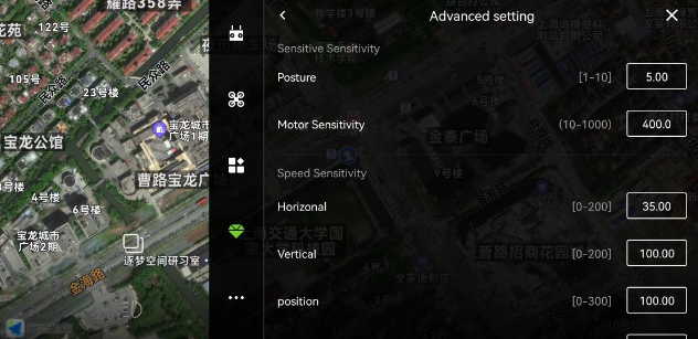
Sensitivity
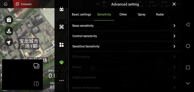
1. Basic sensitivity
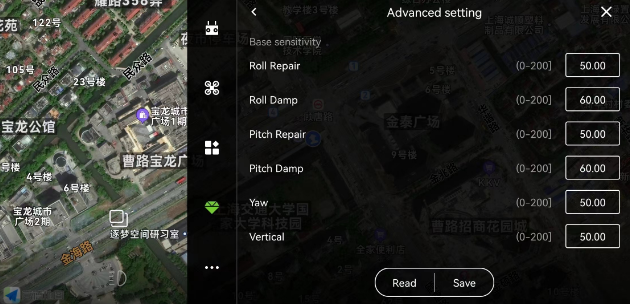
2. Control sensitivity

3. Spiritual sensitivity
For unspecified parameters, select the default.
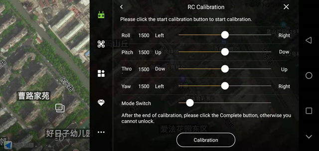
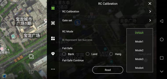
1. Remote control calibration
After the newly installed aircraft, the replacement of the receiver and the replacement of the remote control, the remote control needs to be calibrated. After clicking “Start Calibration”, follow the prompts to operate.
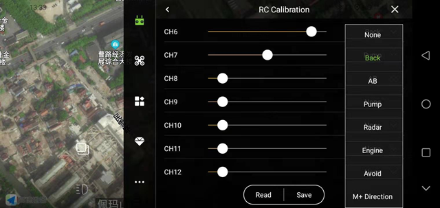
2. Channel settings
You can set the function of each joystick on the remote control. After setting, remember to click “Save” below.
3. Joystick mode
Perform remote control operation gestures for settings, which are divided into: Japanese hand, American hand, anti-Japanese hand and anti-American hand.
1. Sensor
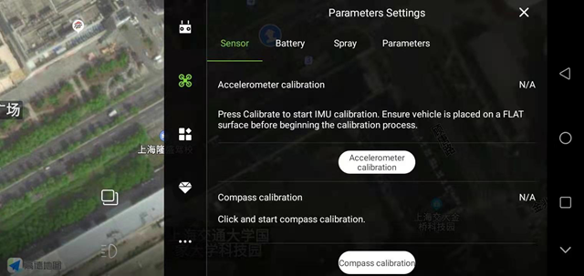
The newly installed aircraft must be calibrated with accelerometer and magnetic compass.
Accelerometer calibration: Click the “Accelerometer Calibration” button, and the calibration will be completed after 3-5 seconds. If the vehicle body is placed at a large tilt angle or shaken during calibration, it needs to be recalibrated.
Magnetic compass calibration: When the flight controller is not unlocked, quickly turn the 5th channel flight mode switch back and forth (or click “magnetic compass calibration” on the APP) to enter the magnetic compass calibration on both sides. The yellow light is always on, and the horizontal calibration is entered. At this time, place the aircraft horizontally and rotate the axis clockwise in the direction of gravity until the green LED light is always on, and then enter the vertical calibration. At this time, the head is facing down and the axis of gravity rotates until the LED flashes alternately in red, green and yellow, and the calibration is completed.
2. Battery settings
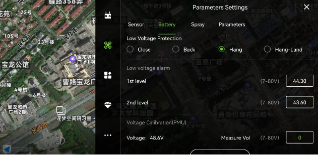
Low voltage protection: When the aircraft is in flight, after the low voltage protection is triggered, it will perform protection actions, including: shutdown, return, hover, and hover landing; generally it will be set to hover.
Take the 12S battery as an example. Level 1 alarm voltage: 44.3V, level 2 alarm voltage: 43.6V.
If the actual voltage of the battery does not match the voltage displayed on the APP, enter the actual voltage value at the measured voltage and click Save to perform voltage calibration.
