Debug
Including equipment: K++ flight control, CAN Hub, imitation radar, obstacle avoidance radar, RTK, KBOX-4, H12 remote control, agricultural assistant APP.
Take the following X4 model and 10KG aircraft as an example. The flight control installation direction is forward and the GPS installation direction is forward; the RTK main antenna is on arm 2 and the secondary antenna is on arm 1 with symmetrical positions;
Please carry out flight control parameter debugging in the following order, (the part marked in red for parameter modification or key confirmation, please install the part marked in red for setting):
①. Computer assistant software download. Enter the official website of Jiyi Robot (http://www.jiyiuav.com/en/download.html), and download the K++ assistant software in the download interface.
②. After installing the assistant software, use the assistant cable to connect the K++ flight controller to the computer. After connection, enter the main interface of assistant software, as shown in the figure below:

Note: Check the version number in the lower right corner: V1.0.4.
③Click “Tools” to enter the tool interface for firmware upgrade, as shown in the figure

④. After the firmware upgrade is completed, the computer assistant software reconnects to the K++ flight controller and starts parameter debugging
⑤. Click “Basics” to set the frames (different models, different choices), installation, power configuration, remote control, sensors, flight parameters interface
Because X4 is taken as an example, select as shown in the figure below

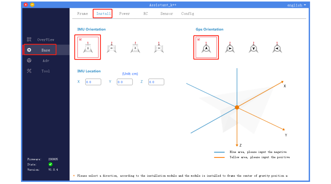
The physical installation is that the flight control installation direction is forward and the GPS installation direction is forward, so make the following choice
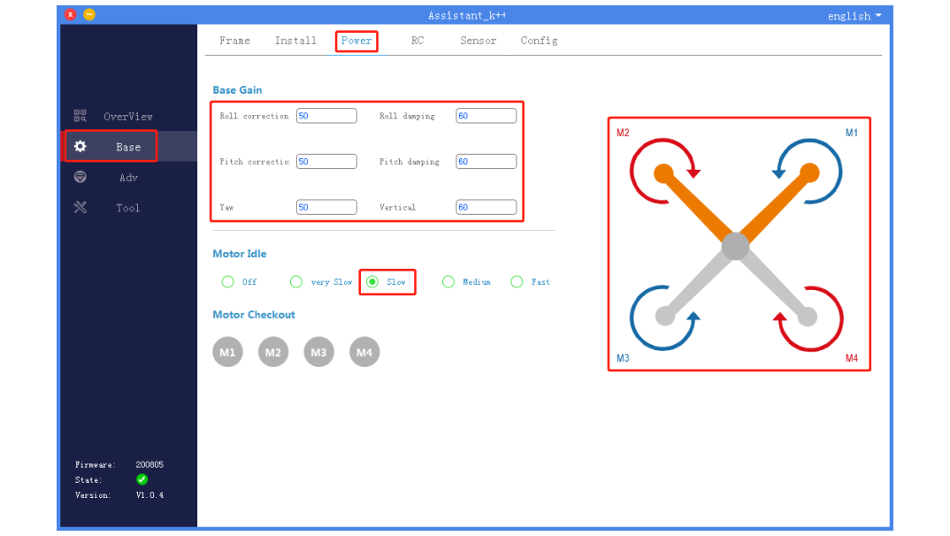
The power configuration is set as shown in the figure below. Roll and pitch correction: 50; roll and pitch damping: 60; yaw: 50; vertical: 50. Motor idle speed: slow speed.
Install the motor blades as shown in the diagram. Do not install them incorrectly.
The remote control is set as shown in the figure below. The flight modes are set separately: ATT, mobile phone operation, AB execution.

No operation on the sensor ininterface

The flight parameter interface is set as shown in the figure below. Maximum tilt angle: 15

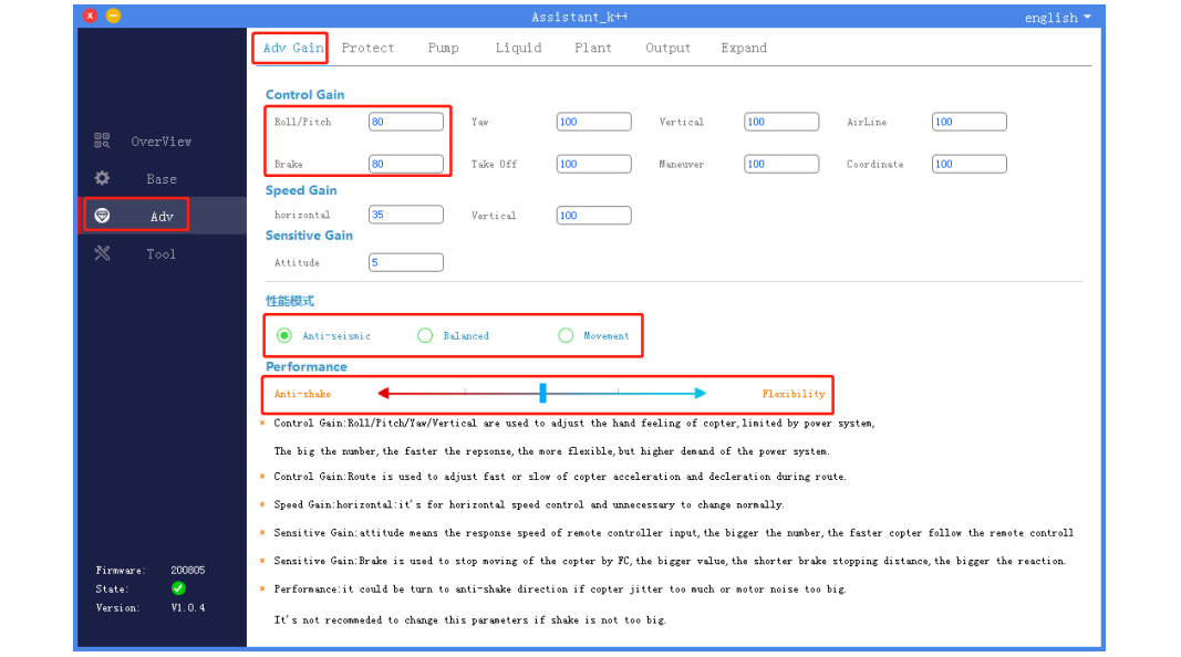
The advanced sensitivity is set as shown below. Roll/pitch: 80; brake: 80; performance mode: seismic mode; performance orientation: neutral. Others need not be changed.
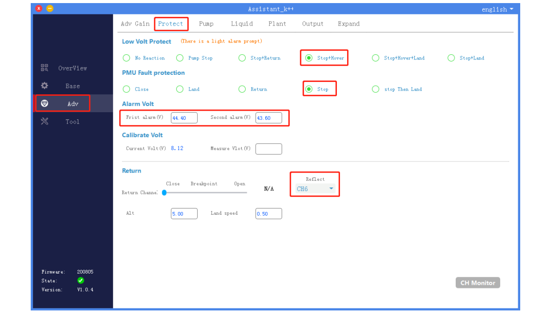
The protection function is set as shown in the figure below. Low voltage protection: pump off + hovering; PMU fault protection: hovering; alarm voltage (12S battery as an example): 1 level 44.3V, level 2 43.6V; the mapping channel of one-key return to home can be set according to personal preference.
The pump settings are shown in the figure below. The mapping channel controlled by the pump can be set according to personal preference.
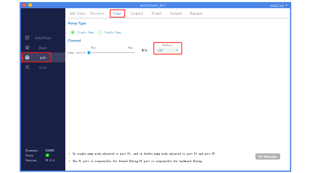
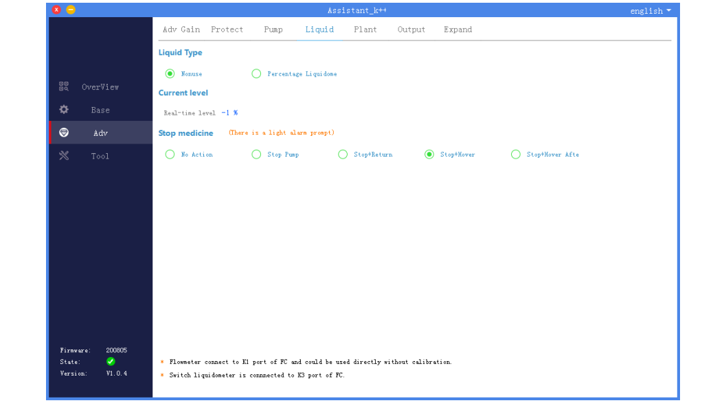
The level gauge interface does not need to be operated (unless the level gauge module is used, select “switch level gauge”).
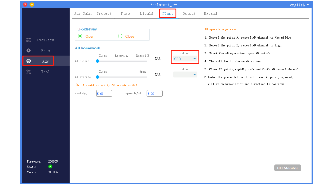
The plant protection function settings are shown in the figure below. The mapping channel of AB records can be set according to personal preference.
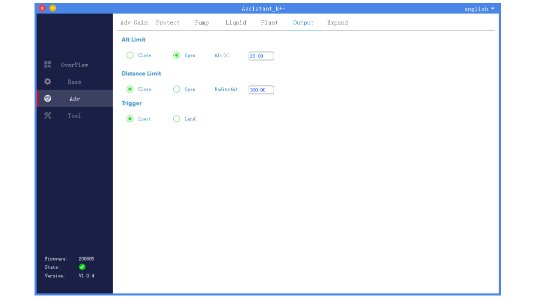
Fence function does not require operation
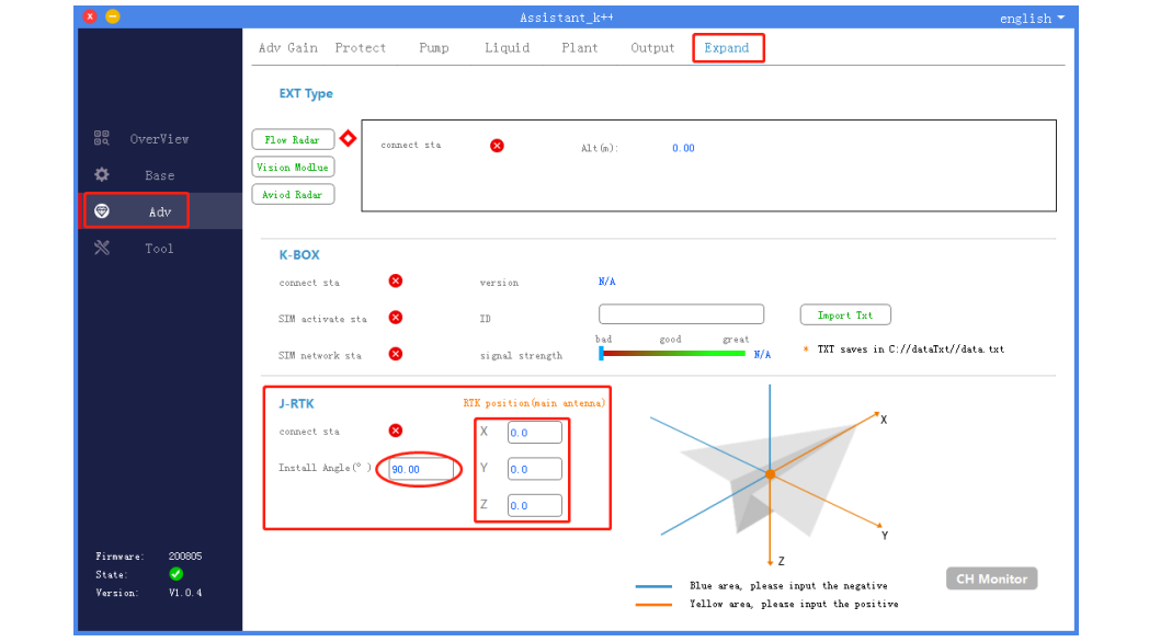
The expansion module settings are shown in the figure below. Installation angle: 90 (for the calculation method, please refer to the RTK instructions); the RTK position is measured and calculated as shown in the figure Setting (mainly the distance setting of the main antenna to the center of gravity)
The tool interface performs the next refresh function verification to ensure that the log can be refreshed.
